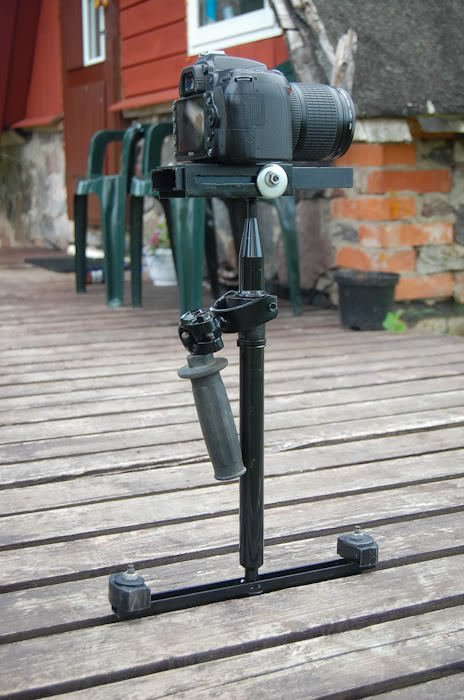
So I had some free time and i figured i could try building a camera stabilizer. Here are a few things i Learned in the process that could have been useful to know before starting.
- Research and patience ! (while i did quite an extensive research, it would be useful to find a photo of the original glide cam and calculate all the dimensions form it (width/height, location of the gimble, etc.)
- Use solid material ( that wont deform and can take some wear and tear (more about that later))
- Do perfect cuts or use ready made pieces to get all joints 90 degrees.
- Get the gimbal axis aligned properly!
- think of ways to build the rig so the calibration is easy (it can take hell of a lot of time and effort!)
- buy a quick release adapter!
Full story of my venture with problems and solutions:
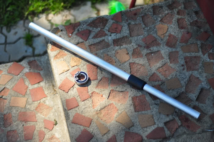
So I started by looking for some bearings and pipes. I found a broom with a telescope handle. I figured it would save me some trouble (bad idea!) and got some bearings from a tool shop. As it turned out though, the handle was too thin. When i beat the bearing onto it, it deformed slightly so the bearing wasn’t on a perfect 90 degree angle, making the rig unstable. The telescope system was also a bit loose and would turn around so i had to keep adjusting it all the time to be aligned with the camera.
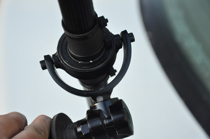
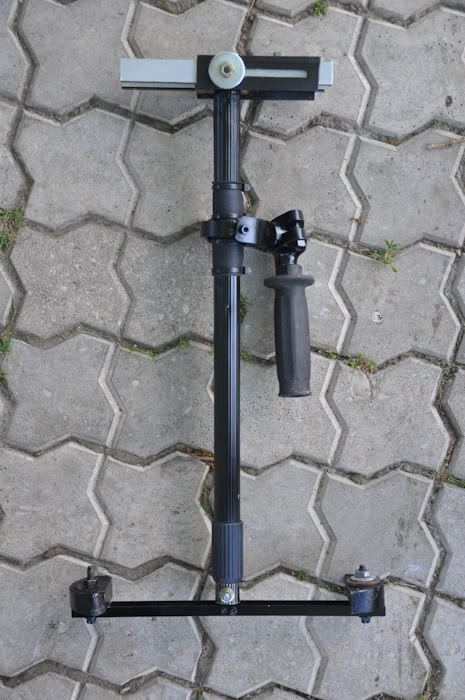
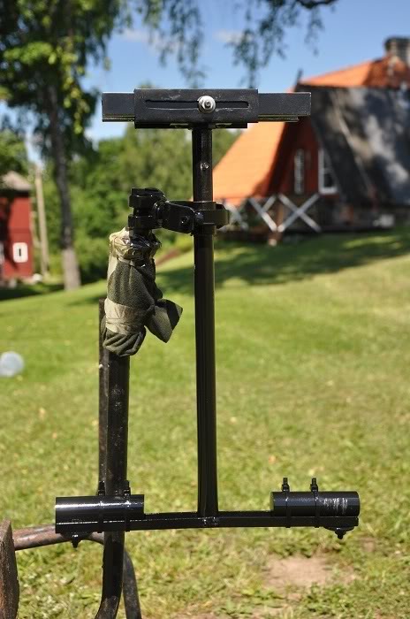
Then on with the gimbal. I cut a piece of pipe to go around the main bearing. Dad helped me to weld it “pockets” for the side bearings and then i beat the main bearing into it. Then we bent the C shape for the back, added another bearing and assembled it all. another word of advice. if you build this from scratch, either do a lot of measuring, use precision equipment or use ready made pieces (like pvc pipes most of these builds are using) otherwise, if you build it with hand drills and welding, the axis are a bit tricky to align perfectly (and if it isnt perfect, the rig will end up less smooth)

For the base, i screwed on a piece of aluminium with pieces of led on each side. Another note in here is to find identical pieces size and weight wise on each side and place them symmetrically.
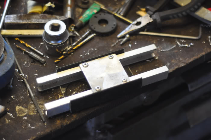
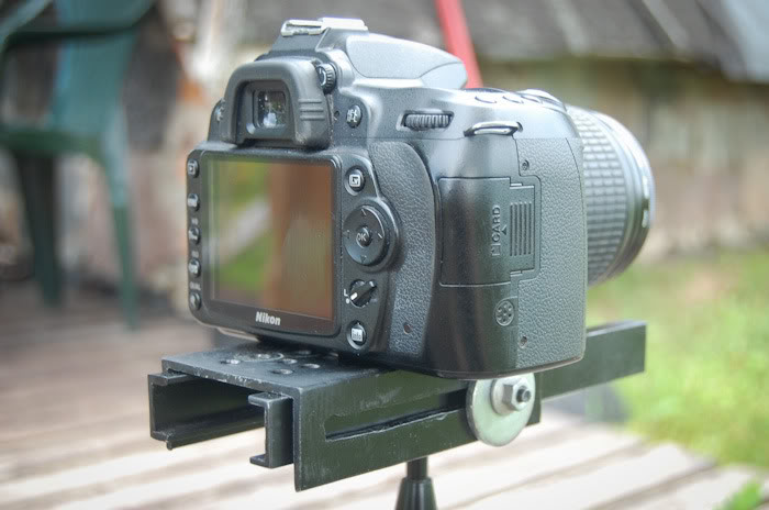
and for the top, i made a slider for front / back balance and series of holes for sideways balance (quick release and sideways slider would be hell of a useful thing too)
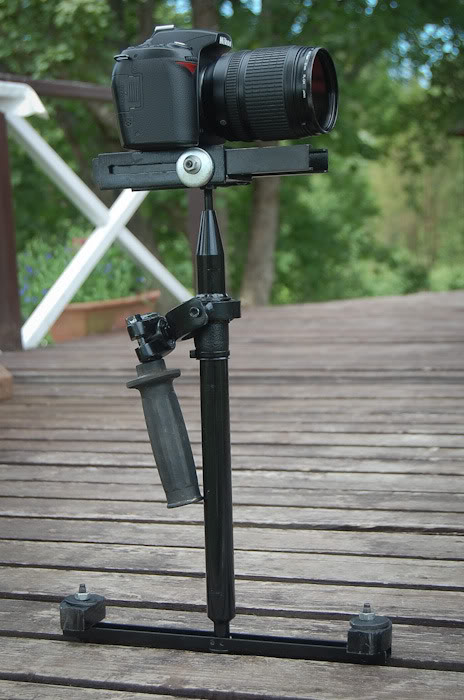
At this point i put it all together. and suprise surprise, i couldn’t get it to work properly.
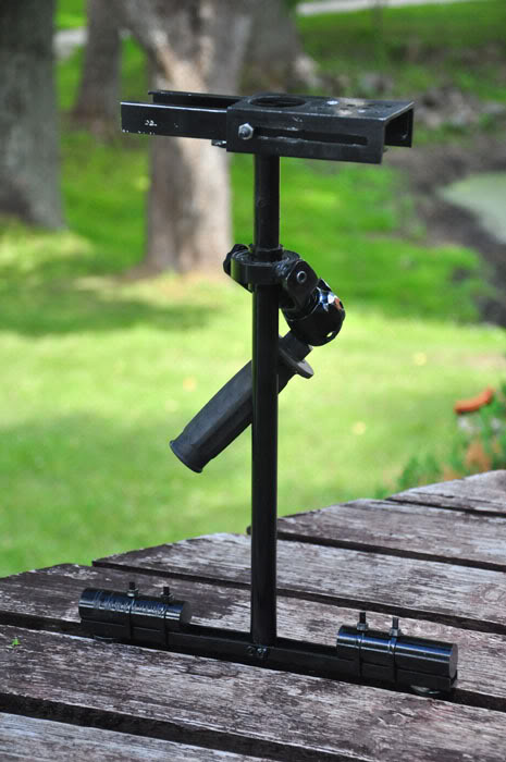
So i figured it must be the handle/gimble relation. i tried finding a new, more solid pipe from around the house. only one that would fit was an old shock absorber… so i replaced the pipes. only to relize that the damn thing was too heavy making the weight of the rig spread out too evenly…

so i found a smaller aluminium pipe and used a piece of the shock absober to fill in the missing space. In the end, it worked pretty ok, one of the axis had an issue where the rig would tilt a lot under a certain angle/handle combo but other then that, its better then my shaky hands.
If i had the cash though, (and no lathe and drill bench at home) i would go for the flycam knockoff from india… less effort and probably more stable. Then again, i also rushed a lot and wasnt that serious about the whole venture but it was fun since i like to tinker and build stuff when ever i get a chanse to come home to estonia.
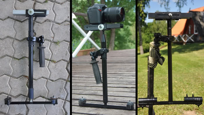
Anyways, you can see it in action here:
very good and excellent and I will try to make it
Hi, saw ur glidecam, it is great!
May i have detail of the material u used for ur glidecam?