
Spent some time building a motorized time lapse rails using raspberry pi… and then used even more time writing the software for it :)
When looking into time lapse rails, i ran across I ran across David Hunt’s post on building a DIY version using raspberry PI. The article was quite nice with a lot of information on the hardware… i however did not want to buy an extra touch screen as was used in that build and running it through command line sounded pretty insane, so i went on to a quest to do something about it :) A couple of evenings later, there was a solution… i put together a little web app that runs on a nodeJS server on the PI which can then be accessed through the browser on your mobile device if it is sharing its wifi with the raspberry.
And since i also had hell of a time trying to piece the whole picture together when building the hardware, then i also figured i should create a dumb down guide which someone with very little knowledge on the subject should be able to follow (there was lots of information on david’s post but it was pretty scattered between 3 posts on several pages, with some info in the comments section and some completely missing… so i had to figure a lot of things out on your own and fill in the caps where i was missing missing something)
Controller software
The software i built can be found in here:
https://github.com/equilerex/PiLapseRails
on that page you can find all the steps you need to go through to get it running on your raspberry along with some more information on how it works/can be used, etc.
in general, theres a few worthy features:
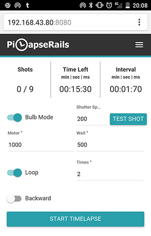
- Remembers settings across sessions (after you restart)
- Configure rail length (will limit the movement accordingly)
- Shots/time/inteval estimation & feedback (according to the rail length)
- configure a lapse by setting the direction, motor length & “wait” length
- bulb mode which lets you define shutter speed
- test shot (when youre testing bulb mode)
- loop (will keep on lapsing back and fourth on the rail)
- manual motor controls (move back / fourth)
- flip motor pins
- etc

Heres an overview of how the software works:
And heres a sample of some time lapses ive done:
Active components | the important stuff
- £30 / £18 | Raspberry PI (model 2 / model 1 maye even zero?) i’ve used PI2
- £5 | raspberry wifi dongle -> make your research first to see if it has proper drivers / support by raspian preferrably with AP mode (hotspot) support… havent tried it myself yet but it would make the connection from the phone much easier
- £1 | 8 X AA 12v battery stack
- £1.5 | remote shutter release cable dependent on your camera -a useful list of different types and their pinouts-
- £3.5 | 6mm rubber timing belt (3d printer replacement)
- Pulley for the belt/motor (buy it along with the timing belt as a set)
- £1 | Strip board (for building the shutter circuit… optional.. can always improvise)
- £1 | 1x 1k Resistor (optionally 2)
- £1 | 1x 10k Resistor (optionally 2) try buying local, often cheaper
- £5 | 1x transistor (optionally 2) with gate threshold of less than 3V (raspberry can supply max 3.3v so it has to be lower than that!) i used model: NTD3055L104G but these components can go out of stock so ask for one with 2.5v threshold at your local electronics store or try to figure it out (this is the hardest component to figure out on your own) you can also try mining for model numbers in the comments here , here and here
- £6 | 12v DC motor | of 20-50 RPM … got 15rpm myself but thats way too slow, i have now ordered myself a variable speed controller and 200rpm motor to try out but will see how that goes
- £2 | Motor controller – ive used L298N as a static switch(on/off).. but its pretty damn large! ive also ordered L293D with variable speed along with new motor so im probably going to upgrade this project soon
- £2 | 12v on/off switch go wild, get something prettehh ;)

The whole assembly will look something like this:

In my layout, there is one extra circuit for “focus” since david referenced Per Magnusson who claimed that Nikon’s remote trigger is trickier than canon and you need to trigger focus,wait for 300ms and then trigger shutter…
maaaybe it depends on your model but in my case (Nikon D7000), it was enough to just connect both focus and shutter of the remote cable to the shutter circuit and as long as the camera was set on manual focusing mode (on the lens or body), it had no problems shooting…
Since i did have the circuit built already, i still left it in and added the logic to the software so you can even select how long you want to focus (maybe if you wanted to use auto settings in case lighting condition were changing a lot?) although the actual lens focus should really be off on time lapses since it is really visible if it shifts around… (been there, done that, had some ruined footage)
If you are planning to be shooting on manual (which you should) then just screw the focus part and ignore it on canon, while on nikon, just connect both focus and shutter to the shutter circuit. As for the rest of the cameras brands… who knows?
The trickiest thing for me in the whole electronics build was figuring out how to connect the mosfet transistor since on normal electrical diagrams (meant for people who actually understand the stuff) the transistor symbol looked very similar to the actual component along with its 3 legs but they really did not reflect the reality… theres a a specific way to read it instead, which i could not get my head around for a while :P
All you need to do is look at the technical document for your specific component to see which of the 3 legs are source, gate and drain. Drain is basically positive, source is negative and “gate” is what enables/disables the connection when power is applied to it
the whole circuit should look like this (the mosfet image is specific to the one i used… they should be more or less similar but check your technical doc first.. often on ebay or google the model number):
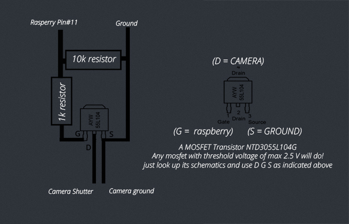
(using the “back plate” for drain instead of the middle leg since it was absent on this model)

and to give an idea of the size of the components:

Rails and slider | The tricky improvising part
This really depends on what tools and materials you have in hand… in general, you should have at least a drill, few drill bits and the basic stuf like pliers/monkey wrench, etc
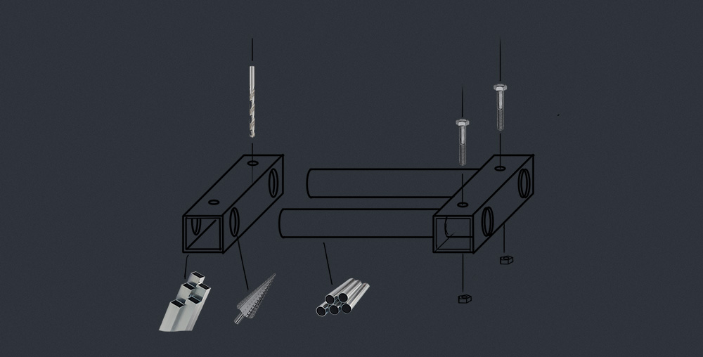
In my mind, the cleanest and most stable way of doing the rail is to got to the local hardware store and get:
- 2x 20mm*1m aluminium tubes
- 1x 25mm*25mm*0.5m aluminium square tube
- 20mm drill bit or step cone drill bit
- 6mm (6m) bolts/nuts/drill
Now cut 2 pieces of the square tube, mine were 12 cm but up to you, mark the center line and make holes at exact same distance on each piece.. then you can slide the pipes through them and to make it more solid, drill vertical holes for each tube and add polts/nuts to fasten it all up
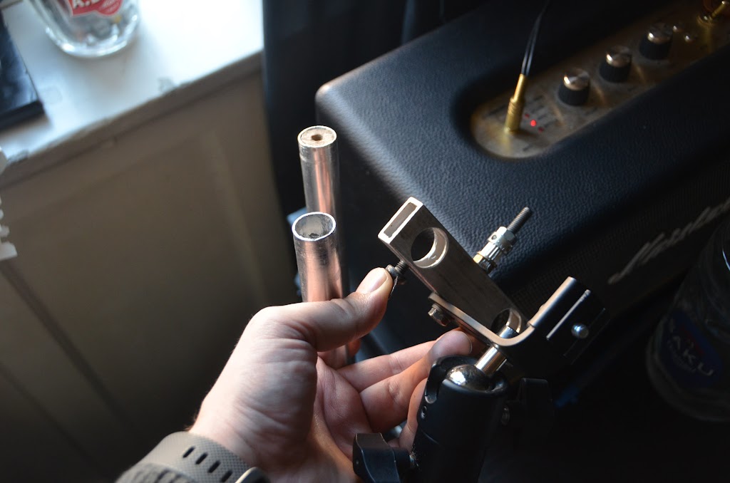
Looks kinda like this (used thiner square tube since i had it on hand but wider will be more stable)
As for the slider itself, you can invent what ever the hell you want (which i did) but in retrospective, i think the easiest and most professional looking solution would have been to just order linear ball bearings (didnt know about them until my friend saw what i had done and then pulled one out of his tool box and said “this could work as well”)
this just needs extra:
- 2-4? Linear ball bearings
- aluminium/steel sheet
- Tripod Ballhead to attach the camera
The whole setup would look kinda like this:

In case you want to cheap out instead and build something on your own, theres many ways, heres a few of my ideas for the layout:

This is how my solution looked like…

And to attach the belt, just use some more bolts and the mounting is totally up to you.. .you can use some static legs, extra tripods, environment, etc

The pulley part itself is fairly simple.. i drilled the engine through the slider plate, attached it with a screw, then i had 2 ball bearings placed a bit lower to create create tension and guide the belt so it would have enough friction to pull heavy loads

in case the system you build is in one piece, just attach the belt permanently. i do that on one side by “stitching” the belt with a solid copper wire but since my system comes apart in order to pack it into a smaller form (the rails can be screwed in half!) then the other side i just fasten with a paper clamp around a spare pulley which creates some extra tension… still trying to come up with a better solution but it works for now.

For housing all the electronics, i used a tin box that my wristwatch came with… fairly easy to work with and with all the plugs and switches in the bottom, it is fairly weather proof… just need to make sure that all the circuit boards are isolated since the metal body is able to conduct current!

The battery i strapped on with velcro and i used a ballhead from an old tripod

And the end result looks something like this:


Hello Joosep !
I liked very much your project it’s very interesting , so i decided to make too , i have followed the steps you have put here as software , until now everything is instaled , i can see in file manager the folders PiLapseRails and quick2wire-gpio-admin_permission created , but when i try to connect to Pi from the phone , in my case 192.168.43.70:8080 , nothing happens , it said page not exit , i can see that Pi is conected to phone’s hot spot … i am newbie in Raspbian so i dont know how to see if the aplication is running , i will apreciated very much if you can tell me how to do it … Thank you , Anton ;
Are you sure that everything worked? from the sound of it, maybe the step for “In order to start the app every time you boot raspberry, we need to add it to the startup process:” from the github page was not applied properly?
To test that theory- while connected to the raspberry with a screen and keyboard, use the command panel to navigate inside the project folder –
” cd PiLapsRails ”
and then try running
” npm start ”
After which the cmd should give some kind of a message about the server running… if thats the case then the auto start is not working ,
if you get an error along the lines of EADDRINUSE then the server is started, meaning that the ip you use is wrong or you have another app already using the port and ip
or if anything else is wrong, it should tell you exactly what is the issue…
Hello again !
I have used the cmd npm start and is an error , i have made a print screen and i uploaded the photo with the entire text so you can see it all , this is the link : https://www.flickr.com/photos/acalpagiu/26921638711/in/dateposted/ … now i am confused about what to do … thank you very much for your response !
from the looks of it, the gpio software is missing… did you miss a step that says:
cd PiLapseRails/
npm install gpio
or was there perhaps an error during the installation of that software?
Did you resolve this – I have the same issue I think! see below
in case you never figured it out, pro-f-sor found the mistake… had mistyple one command… needs to use pi-gpio instead of just “gpio”
Looks pretty cool! Will definitely give this one a try! However, in the example footage you show, there are movements that look like camera shake to me. Was this caused by an instability of the construction itself or by transition parts on the rails maybe? Just asking, because I would like to avoid this, I think the “magic” of it all is to have a smooth linear movement. Also, a 30RPM motor to me seems a bit “fast” or is this stepepd down by the motor controller? Most people use 2 or 1 RPM steppers for timalepse. Sorry for the noob questions, I still didn’t try it out myself and want to avoid making too many mistakes on the way ;-).
Hey, sorry for the late reply… somehow i didnt get a notification :)
most of the sample footage was done before i got a proper tripod solution for it… i was using fairly unstable tiny tripods on both sides back then so most of it is due to that so, definitely not the transition…. also fiddled around with it while it was working since it was still in a prototype state (had not initially done the belt pulley the way its in the photos/diagram so it was creating some issues) and if shooting in a city (especially on bridges) then theres also a lot of vibration from cars and passerby…. all of this can be taken care of in the post-production though with some stabilizing :)
as for the motor, im using 15rpm… it has no problem pulling the fairly heavy load of a d7000 and a tokina 12-4 i wish it would actually be a bit faster so i could do faster loops (where you want to catch people/traffic) 1rpm sounds pretty pointless since you can achieve the same effect by running the 15rpm engine for shorter time-span (lets say 300ms instead of a second) this way you are able to do those ultra slow landscape loops but also faster loops (all the stuff in the samples is around 2 to 5min in real time with usually 1 to 2 second motor bursts)
Hi Joosep,
Awesome! I am building one too! – not reinventing the wheel – just adding water to your recipe. I am getting the ingredients together and I was wondering if I can swap out the Pi 2 for a Pi 3 (has build in wifi and bluetooth). Also looked at David Hunt’s version with touchscreen controller, is it possible to have your software (Wifi control) and that of the touch screen ? (some “hands on” Manual control would be nice) Then I am looking at using a different motor as I want more of a hybrid slider that is capable of doing video and Time lapse shots – with enough speed and torque for both in vertical as well as horizontal axis…and accuracy for the Time lapse – how did your 200rpm and variable speed controller experiment work? I was thinking about using a stepper motor…any recommendations – answers and help would be greatly appreciated.
hey there. sorry for the month delayed reply… seems like i really need to check my email notification settings here :)
it in theory should be possible to have both side by side… might have some conflicts with gpio/pin software but nothing that couldnt be solved (itf there really is any problems at all) otherwise the apps themselves should work just fine.
as for the 200rpm, it didnt go too well… would work on a flat horizontal surface but does not provide enough resistance on tilted setup (camera will just slide down with gravity…perhaps stepper motors or some other solutions might work but a standard brushless dc aint ideal.
Hi Joosep.
Awesome build – so been tinkering away first time in a project like this and had by the sounds of it, the same error the chap at the top had (Anton).
All installed as per instructions, however on Pi3, enable hotspot and entered ip address and nothing!
Checked the install gpio as suggested above and re-installed and then re-ran the npm start and still reporting an error about not finding the pi-gpio???
here’s a link to an screenshot with the error – you can also see the first couple lines were the ‘re-install of gpio and the result message.
I am completely a noob and don’t understand this code but there is a error here and im hoping you can assist.
forgot the screenshot image…here it is: http://tinypic.com/r/2qmf503/9
ahh slight tweak of the install…..
‘npm install pi-gpio’
*adding pi- infront of gpio and it works
Wowsa, that was a bit of a fuckup on my side… sorry for the trouble and thanks for finding that… hadnt even crossed my mind that i had mistyped it :)
Hi,
I love what you have done! I am trying to do something similar but I want to fire the camera using infrared through LIRC. I know rails but it seems most of your code is in js, and I was wondering if you would be interested in helping me modify your code to work with LIRC (infra red LED on pin 16, with the ML_L3 library loaded, the command is irsend SEND_ONCE Nikon2 shutter). I have confirmed this works with Raspberry PI, and thing this would be easier to implement (and may be more versatile for other cameras)
Thanks
from the looks of it, should be doable through this: https://github.com/alexbain/lirc_node
just install the lirc and lirx_node plugins
then add this to the top of http://www.js:
var lirc_node = require(‘lirc_node’);
lirc_node.init();
where ever gpio.write(pinConf.shutter is used, you need to replace it with some custom function that triggers the irc plugin instead
Hi,
This is an awesome project. I am gonna build the same. Instead of DC motor i would like to make a use of NEMA 17 stepper motor (Because I have one). Do you have any idea the same code gonna work with Stepper motor as well to control the motion of my camera.? Any aditional steps that I need to take in order to run the Stepper motor to the same IO of my raspberry? Please advice.
I second that, did u find a solution for this with nema?
Is it possible to put the shutter and focus on the same GPIO pin?
the focus is optional… if your camera “requires” both of them triggered in order to shoot (and you dont want any of the focus delay effects) then just run a wire from the shutter pin to both focus and shutter contacts on the camera wire… will have the same effect ;)
Hi Joosep!
I was just about to ordering stuff to create David Hunt’s Touch version when I found your solution! Now I’ve ordered all the parts and I should hopefully be able to start next week when everything arrives.
Just one question, have you found any solution for this: “wifi can ba a bitch since sometimes the pi just doesn’t wanna automatically connect to your phone… might be good to look into making raspberry the hotspot/access point instead”
Best regards,
Roland Meijer
hey, good luck with the build ;)
unfortunately i haven’t even had time to use the thing since first building it, let alone improve it. from the sounds of it its not too hard to use the pi as the wifi source and then serving a web page from it… just google and follow some answers like this: https://www.raspberrypi.org/forums/viewtopic.php?f=61&t=110184
will most likely be working on the project in the near future… going to see if i can get it using a stepper motor for variable speeds… and i guess trying to do the wifi hotspot as well afterwards but til then, youre on your own unfortunately
OK, cool! I’ll start to get everything working as intended first :)
Have a nice weekend!
Joseph,
I have just built David’s project with a model B pi and it functions and looks quite good. In looking for a more polished option the idea of control via iPhone instead of a touchscreen sounds great so the “computer and boards can be neatly enclosed in a watertight container. That being said, the wifi hotspot is not a viable solution for me due to the limitation of unlimited data on my plan (hotspot is disabled). So a bluetooth option would be fantastic. Is there any chance the code could be modified to support such an option? I also have a ver 3 pi and bluetooth is on that board by default. I would be very interested in the possibility of this, and it could potentially eliminate the wifi problems some have with that connection.
Thanks,
Bill
Hey Bill,
Don’t worry about the data, it’s not using it… Wi-Fi works “offline” as well ;)
Not really worried about data usage. Mobile hotspot is disabled on my account so I can’t create an at-hock wifi network due to my plan having unlimited data. There is no network for the pi to join unless using my pi and phone somewhere there is an existing wifi network to join. In short I can’t utilize the wifi connectivity to join the phone and pi.
So your phone has been screwed over by the service provider to have the hotspot functionality disabled removed? that sounds pretty shitty :/ as i mentioned, it should also be possible to turn the raspberry itself to a hotspot so you connect to it instead… just have not tried it out myself yet.
Great project!
How about the Pi 3? Will it work with the newest version?
Think about buying a Pi 2 or switch to a Pi 3. Any recomendations?
Cheers!
Max
Yes, I’m running PiLapseRails on Pi 3. I finished the electronics part yesterday and hopefully the mechanics of my slider will be finished within a week or two (waiting for parts to be delivered…)
Since you want a shutter speed / interval ratio of 1/2 for timelapse photography most of the time I would recommend one small thing: I would change the wait period before the shot to 1/4 of the interval and after firing the shutter to 3/4 of the interval. Otherwise you are limited in your choice of the shutter speed (In the worst case scenario the motor starts moving before the shot is completed). Another benefit: I want to shoot some stars, therefore I need to have a shutter speed of around 30 sec. To do that with the current configuration I need to set a Interval of at least 65sec (to be sure that the rails isn’t moving while the shutter is fired). If i set the Interval to 65sec I need a LOOOOOOT of time to do the whole timelapse. With the 1/4 and 3/4 config I can set the interval to 45sec. That gives me the opportunity to get more shots out of my precious time ;) The code would look something like this (part of the http://www.js file):
//wait til interval finishes before shooting again
intetvalEvent2 = setTimeout(function () {
//restart cycle
shutterCycle()
}, data.lapseConf.waitLength / 4);
}, data.lapseConf.motorPulse);
});
} else {
stopTimelapse(data.lapseConf);
}
}, data.lapseConf.waitLength / 1.333);
Am I correct? Other than that: THANK YOU FOR THIS AWESOME PROJECT!!!! I’m using it very frequently :)
The http:// has been formatted badly by the browser…
Hey, glad to hear it has been useful :) and sorry for the late reply traveling SE Asia for the next 2 months. If I remember it correctly(can’t really check the code on the phone) the shutter speed and motor pulse are fired one after another, not asynchronously… So if you leave “delay” 0 then it should shoot with interval ratio of 1/2… The “delay” feature was mostly because my rails would shake a tiny bit when it stopped… So if I added a second, it would use half of it before and after to stabilize. On the other hand, it could also been used for longer timelapses
Hey,
Fantastic write up, been working with the software while waiting on some parts. For anyone else interested, I was able to put my Pi 3 into hotspot mode via this tutorial: https://frillip.com/using-your-raspberry-pi-3-as-a-wifi-access-point-with-hostapd/ and it works just fine. Not sure which method is more reliable or it’s effect on battery life. I did this because I’m not sure if my phone can start a hotspot in places without reception (Maybe it does, but it doesn’t work in airplane mode with wifi on)… But it also useful if you cannot do hotspot on your phone, and it let’s you use any device to remote control the rig without having to tweak SSID/pass to match whats saved in Pi.
Also just curious, Joosep did you find the BLDC motor performance to be adequate? I’m asking since you are already using the the L298N which is also capable of driving a stepper motor which would probably be more precise in terms of distance traveled?
Nice! Will try the hotspot out myself as well then, thanks for the link. Motor wise, I am not actually sure. It works fine in terms of having a smooth, consistent movement but it sometimes has issues knowing where on the rail it is located on (so it would trigger back and fourth at the right time) but I don’t think it has to do with the motor, rather than with the construction of the rail… I usually take my rig apart when moving around and I also made the attachment points of the belt too much in the middle so it’s not completely parralel withe the slider attachment point which creates SE unwanted tension and sometimes the gears skip a few teeth
Hi!
First of all thanks for the tutorial. I was about to make David’s touchscreen version of the controller. Actually got it working without a touchscreen (via vnc) and controlling it with iPhone. Then I ran to your blog and saw that this might suit me better. Keep the boot time lower etc with booting it in to command line only. I have the pi making a hotspot with a static ip. It’s the first model B with an asus wifi-dongle. You have to be careful what dongle you use, cause of course not all of them work as a hotspot for some reason. The setup for the it was the same as in Tony’s link one post up. Of course no need for ipv4 forwarding or dnsmasq.
One thing I would really like is to add a switch to stop (or to reverse) the movement at both ends of the camera dolly to avoid accidentally running out of rail. Not good for the motor or the belt to struggle at the ends and start slipping when it hit’s the end of the rail. I know it isn’t a big problem, but the thing is that the rail length in milliseconds is quite different for me if it’s going a slope up or down. Obviously going up takes longer and longer when the angle gets more steep and the opposite for downwards movement. Is it just a problem with my motor or is anyone having the same problem? Even took the battery pack of the dolly to get it lighter. I’s really hard to loop the movement, with the different leghts fot up and down. Could the switch set the remaining rail lenght to zero somehow so it would start looping if it’s enabled? The problem is that I’m a total noob with code so don’t really now how to approach this. I’ve only done some simple things with python.
Thanks!
-Antti
Hey, glad its been of use and yeah the milliseconds are perhaps not the best solution if the construction is not spot on (loose belt or weak motor) in which case i guess mechanical switches would also reduce the hassle on the setup and when things go out of sync (though that would also mean no estimates on how many shots and how long the shoot will be) could even add a few more buttons to make it fully self sustained with no need for the phone.
on the other hand, i will be implementing an option for a stepper motor sometime soon which should (theoretically) be more accurate than the cheap dc motor’s and also provide variable speed though even then a safety switch could be nice to have so i will most likely be implementing an optional feature for that as well
Hey!
Thanks for the fast reply!
I know the mechanical switches cause a problem with the amount of frames and the total time. I could live with that for now though. I like the idea of a geared dc motor cause it’s just so simple and doesn’t use any power to to stay still on steeper climbs. Haven’t used stepper motors on any project so I’m not that familiar with them, but don’t they require some sort of electrical braking to allow them to hold position on climbs?
Just ordered a smaller pulley for the motor, cause they are just a few euros from China. Might help a bit, but we’ll see. Might eventually replace the motor to a stronger one or maybe to a stepper one who knows. The belt is tight enough, so I haven’t had problems with slippage etc. It can do a vertical climb for that part. The motor can lift the dolly with the camera, but I can’t do longer exposures cause the motor can’t quite hold the weight. Starts really slowly sliding down.
My rail design is totally different btw. It’s basically a 2m aluminium door rail cut in half, bolted together back to back and a couple sets of wheels meant for a sliding door. Had to add four bearings on top of the rail to remove wobble. The body of the slider is a 10x20cm nail plate and the wheels and bearings are attached with angle brackets. Just went through the local hardware stores to find the parts. Cause it doesn’t need basically any clearance beneath it, I can easily clamp it to a beam or a patio railing for example. One end of it has couple angle brackets bolted together so I can attach a tripod to it and the other has a 25cm piece of wood attached to an angle bracket that I can tilt for adjustment. What I haven’t yet tested is attaching it to a tree with ratchet straps ;) The rail, a tripod and a couple small bar clamps fit nicely in a padded bag for a bass guitar. So it’s quite easy to haul even though I can’t tear it down. Might do a more compact travel version later on with a different design. Electronics are in a plastic lunchbox. At least for now. It’s still bit of a work in progress, but I’m quite happy with it.
Here’s some photos of the rail if anyone is interested: https://www.dropbox.com/sh/7w5obhemf6ubexq/AACULZRrCX9FDMheDhbt1jLVa?dl=0
Good to hear you’re continuing the development!
-Antti
PS. Btw Joosep, I’m the same guy that did the drunkish-lapse last Friday after karaoke. Posted it Saturday to Instagram and mentioned you in it.
PPS. Sorry for the long post!
Hi,
i recently made a slider rail using your setup. I made the parts with a 3d printer. I wanted to make an portable but extendable slider. (im traveling to norway/sweden this summer and i want to vary in rail lenght) So i used standard 15mm pipes. Im really happy with how the slider turned out.
FIrst, i made some mistakes in printing (tolarances/wrong holes etc and it was all wobly..nothing a stabilzer can’t fix, but still i wasnt happy.
Also the attachment to the quickrelease plates weren’t too strong… So i started again with a new design.
This one works perfectly and is powered by a spare 12v battery wich i had laying around.
It’s setup to use my phone’s hotspot (simply by setting up the wifi when the pi first booted, before i started your installation manual)
For camera i use an Sony a77 (some focus problem, but i want to shoot in manual anyway…)
Here is an googledrive link to some pictures, the first 2 tests and the stl files. I think i might upload these to thinyverse, with an link to your project if thats ok!
https://drive.google.com/drive/folders/0B-7ouIVrxejYbDB0aEdhOG1kaFU?usp=sharing
I read every comment here and saw that you’re planning on implementing an stepper!!! that would be so awesome!!!!! I will use this and make a new stl file!
In future is it possible to ad an second motor for panning/tilting purposes??? i’m good with hardware/electronics but not with code…
Thanks for you’re super project!
Giel Greijn
That’s a pretty badass solution! Very nice, might actually consider a remake of the rail as well… Motor in the end and exchangeable rails seem pretty nifty. And yeah, will try out the stepper and see if it has enough power to keep the slider in place… Probably going to happen within the next month or two. Secondary motor should be pretty simple to implement as well so will look into that :)
Hi Joosep
First of all… what a great project and thanks for sharing with everyone. It has inspired me to have a go myself. Slightly different situation as I already have a secondhand Konova slider that I bought on eBay a while ago. I am planning on purchasing their K-Motor 250 (which is £115 new but will hopefully save some hassle and work well) and then going to try and build a controller with an old B+ I already have. http://amzn.eu/fywCHIt
It appears to be a DC motor and has limit switches built in. The UK distributor will not give me technical details of the inputs/outputs but hopefully I can work this out.
On the electronics side you said you were upgrading to a L293D… how did that go? Is there any difference from a software perspective?
Anyway, keep up the good work,
Ross
Such an amazing tutorial! I have little electronics knowledge beyond building PC’s, but you’re details on the circuits and electronics has encouraged me to give it a go!
While waiting for all the ebay parts to arrive, I’m working on the rail. I was hoping you could give some insight in to the center plate you installed that allows a center tripod mount for the rail. I’ll be doing mostly astro timelapses, and really like the idea of only needing to bring a single tripod with me up mountain peaks.
I also like the idea of using linear ball bearings, but I can’t seem to figure out an easy way to incorporate that center plate with those block shaped bearings. Cost wise, I have a set of skateboard bearings I can use so weighing the pros and cons of going with linear bearings.
Thanks again, for your article, and any help you can provide!
J.
Good to hear it has been helpful :)
i would say avoid the single tripod combo… way too unstable and needs a lot of over engineering and a huge tripod to make it happen. in most cases you would place one side of the rail close to the ground anyways so you can still get away with just one tripof in one end of the rail.
linear bearings usually have threaded holes on the top… so all you need is trilling holes in the center plate and screwing some small bolts through those… much easier than building something from scratch
Hi Joosep,
after few months reviewing your tutorial, I now have all the pieces and starting to sold everything together.
However, I did acquired the “Expansion Board Uno Shield Motor Drive For Arduino Duemilanove Mega L293d Diy H” and now wondering which of the pins from that Shield motor drive will correspond to your “Motor A and Motor B” connecting to Pi pins 11 and 12?
Great tutorial, learned a lot of things, and quite excited to see that pilapse rail working for next summer!
Many thanks.
Ben
Hello, great tutorial i made a conversion myself with a dc 100rom motor and l298 it worka ok.
My questio is it possible to add a control for a second motor movement i would like to add a camera paning while sliding.
Also is it posible to trigger also a phone s camera like an app that can be triggered if vol up is pressed?
Thank you
Hey Joosep, thanks for this kind of detailed descriptive tut!
How do you power Raspberry pi? Does it get power from pins 15, 16 or do we connect separate power source to it?
Thanks, Shri
hey, sorry for the late reply. right now i power it with a 5v powerbank for phones, next version i will use a car usb adapter to take the powere from the same 12v source though
Hey thanks to clarify that. Appreciate it!
I bought a buck down converter from ebay and been really happy with it. Dirt cheap and works really stable. I’m going straight into to the gpio cause it was way easier to do. Also using the usb was hard for casing everything. Using an old B so haven’t been that worried of frying it. Of course measured the voltage when I got it. Haven’t had any problems except that It was hard to mount it anywhere cause it’s so small and has no screw holes. So I put it on the same circuit board with pin headers as the shutter control. Four wires from it to the gpio and I have power input and shutter/focus control.
Just got the electronics repacked more neatly into an old us army ammo box. Used old casings from broken electronics for the circuits and attached them with velcro ;) Also added an 12v 9ah gel battery at the the bottom, cause got fed up with using aa-batteries. A heavy duty power bank with 12v out would have been a smarter choice weight and performance wise, but there’s always room for improvement. Gel batteries are ridiculously cheap though and can be easily and quite safely charged for example from the cars lighter socket. Also added an adjustable step down converter to it so now I can power my camera through the same battery too if I wanna do longer lapses. I cased it into an old power supply box and made it easily detachable so as a bonus I can power the camera from basically anything above 9V and 2A. It also has a nice lcd-display that can monitor the input/output voltage so I know how my battery is doing. Got it also from ebay.
Here’s the buck down converter:
https://www.ebay.com/itm/1Pcs-Mp2305-Dc-Dc-Buck-Sent-Down-Converter-Module-7-20V-12V-19V-To-5V-2A-Car-I-D-/332193138347?hash=item4d584106ab:g:74EAAOSwcLxYHcb5
..and the adjustable one:
https://www.ebay.com/itm/32V-5A-Step-down-Adjustable-LCD-Digital-Power-Supply-DC-DC-Converter-Module-J9H2/331979011109?ssPageName=STRK%3AMEBIDX%3AIT&_trksid=p2057872.m2749.l2649
Thanks again for the tutorial. Even though I’ve connected the gpio cables countless times I usually come here for a cheat sheet ;)
Hi, this tutorial is really good. I’m building this slider as well only using carbon fibre tubes for the rails. Just wondering how difficult it would be to add a second axis say a panning motion to the slider? thanks.
Hello Joosep. This is great, it is excellent to have a handheld controller for the time lapse control.
Now that the Raspberry Pi Zero W is out I am trying that machine as my controller as it has WiFi and Bluetooth embedded.
I am having an issue with the install and was not sure if the version of Raspbian I am using may be the problem.
I have loaded Raspbian Lite (not NOOBS version) to keep the overhead down and that is all functioning as expected.
Following the instructs and everything is successful until I get to the command ‘npm install’ and it harks out errors and goes no further.
The error is about missing ‘node’? I tried to reinstall and make everything again but it says it is all up to date and already at the latest version, etc.
The error (same as in the npm-debug.log)……..
> node-sass@3.13.1 install /home/pi/PiLapseRails/node_modules/node-sass-middleware/node_modules/node-sass
> node scripts/install.js
sh: 1: node: not found
npm WARN This failure might be due to the use of legacy binary “node”
npm WARN For further explanations, please read
/usr/share/doc/nodejs/README.Debian
npm ERR! node-sass@3.13.1 install: `node scripts/install.js`
npm ERR! Exit status 127
npm ERR! Failed at the node-sass@3.13.1 install script.
npm ERR! This is most likely a problem with the node-sass package,
npm ERR! not with npm itself.
npm ERR! Tell the author that this fails on your system:
npm ERR! node scripts/install.js
npm ERR! You can get their info via:
npm ERR! npm owner ls node-sass
npm ERR! There is likely additional logging output above.
npm ERR! System Linux 4.9.41+
npm ERR! command “/usr/bin/nodejs” “/usr/bin/npm” “install”
npm ERR! cwd /home/pi/PiLapseRails
npm ERR! node -v v4.8.2
npm ERR! npm -v 1.4.21
npm ERR! code ELIFECYCLE
npm ERR! Additional logging details can be found in:
npm ERR! /home/pi/PiLapseRails/npm-debug.log
npm ERR! not ok code 0
Not sure how to proceed. I will download and install the full version of NOOBS and try again in case there is some missing package(s) that npm is dependent upon.
Thanks for this great article and any help you may provide!
best regards, Jon
Hi, it is possible generate a code to add one motor off the panning mode?
And , i have a question.
My camera doesn’t detect the focus mode, the signal is used for shutting a camera. I tested the circuits and it shows the good mode. Maybe the camera is sensitive for the focus mode